 English
 Deutsch
 Espaniol


We all know that different types of optical fiber cables are used for communication and connectivity between devices like routers, switches, transceivers, etc. Generally speaking, these cables are terminated through optical connectors, and in a few cases, splicing is preferred. Return Loss (RL) and Insertion Loss (IL) are two critical parameters that give us information about the attenuation effects across fiber connectors.
What is Insertion Loss (IL)?
In the telecommunications industry, insertion loss is a term used to indicate the losses in signal power and it is indicated as a ratio (in decibel or dB). We can easily calculate insertion loss by inserting a device in an optical fiber link or transmission line. Insertion loss can also be termed as “attenuation”, which shows the total signal loss and it is measured by comparing the supplied power to the output power. It is important to understand that a higher insertion loss value indicates a poor insertion loss performance I.e. an insertion loss of 0.2dB is better than 0.6dB.
What is Return Loss (RL)?
In any optical fiber transmission line, a certain number of light rays tend to reflect and return to the point of origination or source because of inherent discontinuities and impedance mismatches in the Return loss is a term that can be defined as the loss of power in the signal reflected or returned by a discontinuity in an optical fiber or transmission line and it is denoted as a ratio in decibels. A high return loss is considered a good indication because it shows that the lines or devices connected through lines are well matched. In any optical fiber transmission line, a certain number of light rays tend to reflect and return to the point of origination or source because of inherent discontinuities and impedance mismatches in the Return loss is a term that can be defined as the loss of power in the signal reflected or returned by a discontinuity in an optical fiber or transmission line and it is denoted as a ratio in decibels. A high return loss is considered a good indication because it shows that the lines or devices connected through lines are well matched.

What Causes Return Loss and High Insertion Loss?
Hypothetically speaking, an optical fiber link stretched through point A to point B without any intermediate connector and interruption can ensure minimum or even zero losses. However, it is impossible in real-world networking environments because connectors are of vital importance. Let us talk about a few important factors that can help us in achieving optimum IL and RL performance.
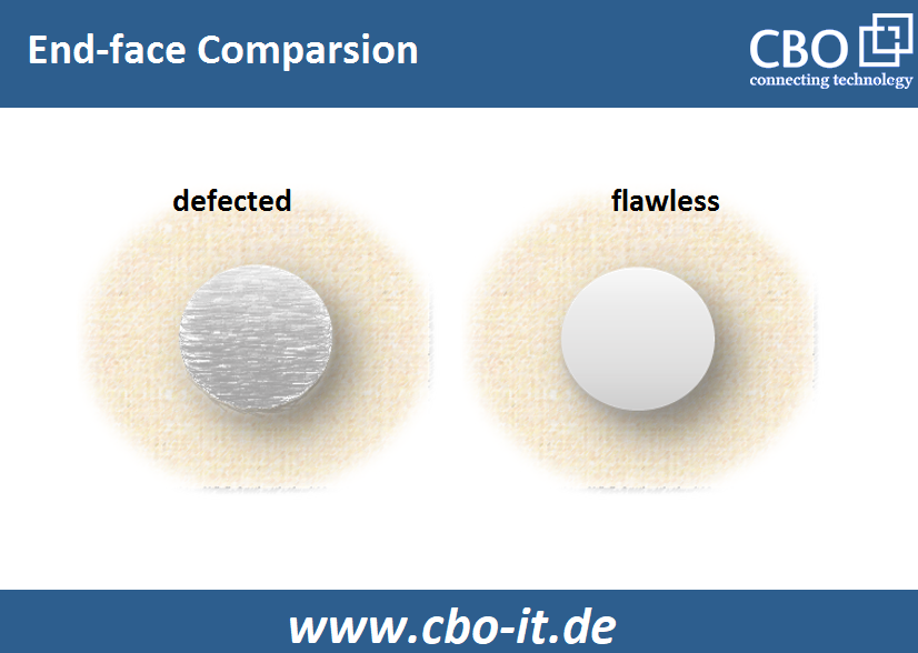
End-face Cleanliness and Quality
It is a fact that fiber end-face defects such as cracks, contamination, and pits will bring a direct and devastating impact on the link performance. Through experiments, it is learned that poorly polished or irregular fiber end-faces can lead to higher return/insertion loss. In an optical fiber link, any irregularity that impedes the transmission of light from one fiber to the other will degrade RL and IL.
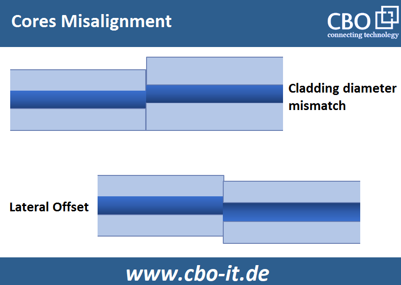
Misalignment between the Cores
It is quite understandable that the main function of the optical fiber connectors is to keep the associated fibers in an optimum, precise position to ensure that their cores are completely and accurately aligned. So, connectors are manufactured with a lot of care and precision. In ideal scenarios, a hundred percent core-to-core contact should be achieved through a pair of coupled connectors. In this regard, it is important to understand the role of a very important component called “ferrule”. It is quite obvious that an imperfectly centered ferrule bore cannot keep its host fiber in a perfectly centered position resulting in losses. Even if one of the two optical fiber connectors joined through a coupler can bring a degrading impact on the overall performance of the communication link. So, poor IL/RL cannot be avoided in case if the connectors utilized are not capable of keeping the respective fibers held in the correct position.
Poor Contact Between Cores
To achieve the desired high RL and low IL, optimum core-to-core contact must be maintained. Different fiber connector polishing styles offer varied intra-core contact performance. In typical operating conditions, the insertion loss of UPC, PC, and APC connectors remains
How to Reduce Connector Related Losses?
Well, we can construct and operate an optical fiber network by using high-quality and well-tested connectors. besides this, you can achieve better network performance by complying with the following general guidelines:
- Keep all the connectors clean, especially during and after the testing and installation
- Avoid use makeshift tools and always keep yourself aligned with vendor guidelines
- The use of improper tools is a no-no
- Try minimizing or limiting the number of tight coils, splices, connectors, and bends which may force light to refract through the cladding.
- Prefer factory terminated cables as these cables are; designed and manufactured under strict guidelines, tested before getting dispatched, and offered with a warranty
- Always go with realistic budgeting when it comes to cabling. Cheap optical fiber cables or connectors may trigger unwanted downtimes and monetary losses in the longer run
Conclusion
IL and RL cannot be eliminated but we can construct and operate an optical fiber-based communication network by choosing the right type of cable and connectors. we can achieve better performance and efficiency by evaluating both return loss and insertion loss.


