 English
 Deutsch
 Espaniol


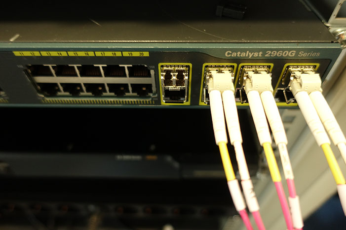
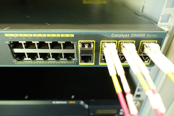
SFP, SFP+, QSFP, XFP transceiver modules are hot-swappable I/O devices, which are the key components in today’s transmission network.
Compatibility Check of SFP / SFP+ Modules
Before making any change or replacement of the transceiver component we must be sure to have a fully hardware compatible module when using it with the hosting equipment such as switch/router or optical transport network equipment. Some Cisco networking equipment for example will accept only CISCO sourced optical transceivers through an initial firmware compatibility check at the time of insertion. Only SFP / SFP+ modules that pass this check are usable. There are two undocumented commands which can be used to force the Cisco Catalyst switch to enable the GBIC port and use the 3rd party SFP / SFP+.
General safety measures for SFP / SFP+ Modules
Before any remove or install of an SFP / SFP+ module, we need to protect the SFP / SFP+ modules by inserting clean dust covers into them after the cables are removed. We need to clean the optic surfaces of the fiber cables before plugging them back into the optical ports of another SFP / SFP+ modules. Avoid getting dust and other contaminants into the optical ports of your SFP / SFP+ modules, because the optics will not work correctly when obstructed with dust.
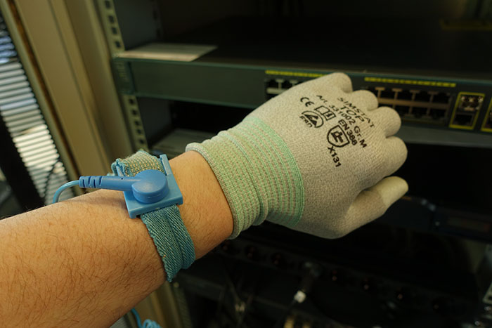
It is strongly recommended that you do not install or remove the SFP / SFP+ modules with fiber-optic cables attached to it because of the potential of damaging the cable, the cable connector, or the optical interfaces in the SFP / SFP+ modules. Disconnect all cables before removing or installing an SFP / SFP+ modules. Removing and inserting an SFP / SFP+ modules can shorten its useful life, so you should not remove and insert SFP / SFP+ modules any more often than is absolutely necessary. A wrist strap or similar personal grounding device designed to stop ESD occurrences must be attached before touching the modules.
Mechanical fixing mechanism of SFP / SFP+ Modules
SFP / SFP+ modules use one of four different latching devices to install and remove the module from a port. The four types of SFP / SFP+ modules latching devices are described.
- Bale Clasp SFP / SFP+ modules
- Mylar Tab SFP / SFP+ modules
- Actuator Button SFP / SFP+ modules
- Slide Tab SFP / SFP+ modules
Removing and Installing SFP / SFP+ Modules
The duplex LC connector on the SFP / SFP+ transceiver modules support network interface cables with either Physical Contact (PC) or Ultra-Physical Contact (UPC) polished face types. The duplex LC connector of transceiver modules do not support network interface cables with an Angle Polished Connector (APC) 8° polished face type for direct connections. The 10-Gigabit SFP+ transceiver module is a hot-swappable I/O device that plugs into 10-Gigabit ports. The SFP / SFP+ transceiver module connects the electrical circuitry of the system with the optical network.
How do I install SFP / SFP+ Transceivers?
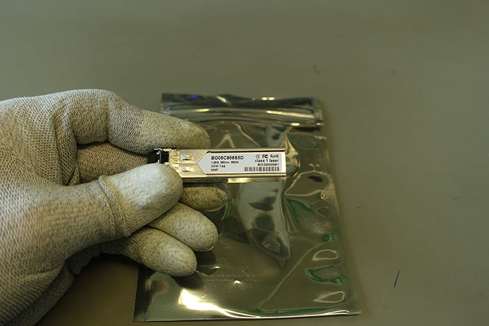 Step #1 Remove the SFP / SFP+ transceiver from its protective packaging
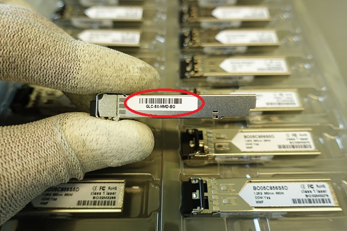
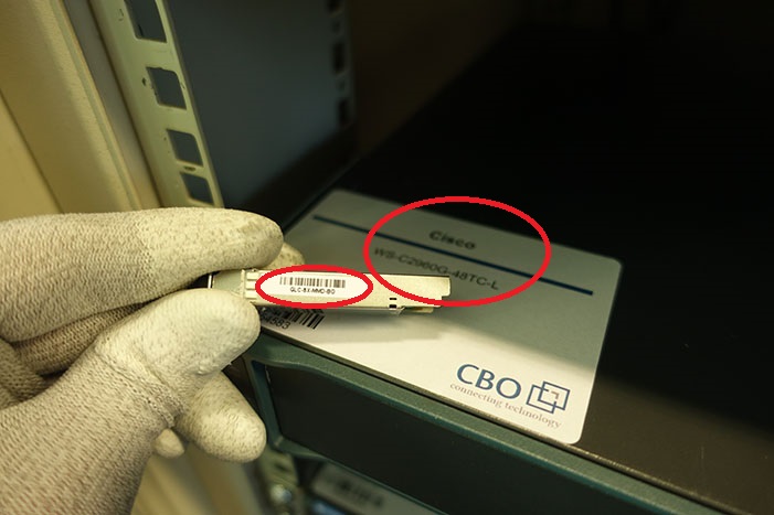 Step #2 Check the label on the SFP / SFP+ transceiver body to verify that you have the correct model for your network.
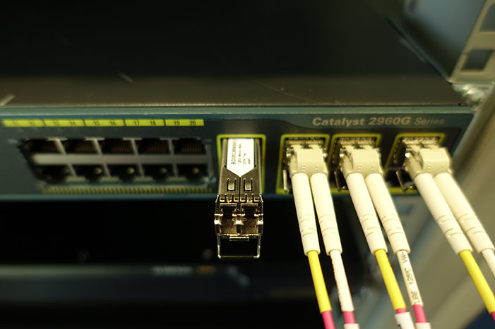 Step #3 Position the SFP / SFP+ transceiver in front of the SFP / SFP+ socket opening on the module. Slide the SFP / SFP+ transceiver part of the way into the transceiver socket on the system module front panel.
Step #4 Remove the optical bore dust plug from the SFP / SFP+ transceiver.
 Step #5 Pivot the bale clasp up so that it is parallel with the transceiver body
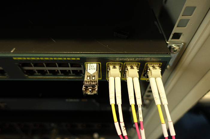
 Step #6 Continue sliding the SFP / SFP+ transceiver into the socket until the SFP / SFP+ transceiver is mated with the transceiver socket connector
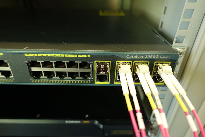
 Step #7 Latch the SFP / SFP+ transceiver in the transceiver socket by pivoting the bale clasp down so that the bale clasp is perpendicular to the transceiver body
Step #8 Immediately reinstall the dust plug in the SFP / SFP+ transceiver optical bores. Do not remove the dust plug until you are ready to attach the network interface cable
How do I remove a SFP / SFP+ Transceiver?
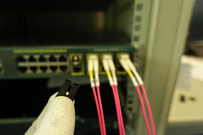
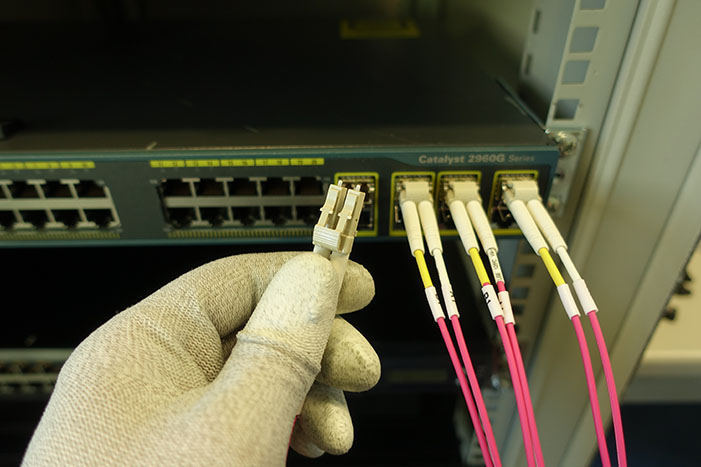 Step #1 Disconnect the network interface cable from the SFP / SFP+ transceiver connectors. Immediately reinstall the dust plug in the fiber-optic cable LC connector
Step #2 Pivot the SFP / SFP+ transceiver bale clasp up to release the SFP / SFP+ transceiver from the socket
Step #3 Slide the SFP / SFP+ transceiver out of the socket. Pivot the bale clasp down and immediately install the dust plug in the SFP / SFP+ transceiver optical bores
Step #4 Immediately place the SFP+ transceiver in an antistatic bag


