 English
 Deutsch
 Espaniol


The CWDM transceivers are working in a specific optical frequency ranges defined by the ITU-T. In 2002 the ITU standardized a channel spacing grid for use with CWDM (ITU-T G.694.2), using the wavelengths from 1270nm through 1610nm with a channel spacing of 20nm.
Each transceiver module typically contains a laser transmitter circuit capable of converting electrical signals to optical signals, and an optical receiver capable of converting received optical signals back into electrical signals.
Typically, a transceiver module is electrically interfaced with a host device — such as a host computer, switching hub, network router, switch box, computer I/O and the like — via a compatible connection port. Moreover, in some applications it is desirable to miniaturize the physical size of the transceiver module to increase the port density, i.e., and therefore accommodate a higher number of network connections within a given physical space. In addition, in many applications, it is desirable for the module to be hot-pluggable, which permits the module to be inserted and removed from the host system without removing electrical power.
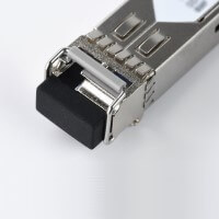
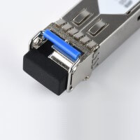
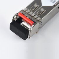
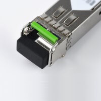
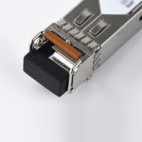
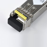
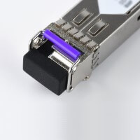
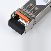
For practical purpose the frequency range has been represented by the equivalent colors according to the spectral color of the light, which can be found at the bail color of an optical transceiver (such as SFP, SFP+, XFP, QSFP, SFP28, QSFP28). In such a way, the technician can identify at the rack and in the spares the desired frequency for the system by picking up the corresponding color.
CWDM Wavelength and Bail Color Definition
| Channel No. | Central Wavelength (nm) | Bail Color |
|
27 |
1271 |
Grau |
|
29 |
1291 |
Grau |
|
31 |
1311 |
Grau |
|
33 |
1331 |
Violett |
|
35 |
1351 |
Blau |
|
37 |
1371 |
Grün |
|
39 |
1391 |
Gelb |
|
41 |
1411 |
Orange |
|
43 |
1431 |
Rot |
|
45 |
1451 |
Braun |
|
47 |
1471 |
Grau |
|
49 |
1491 |
Violett |
|
51 |
1511 |
Blau |
|
53 |
1531 |
Grün |
|
55 |
1551 |
Gelb |
|
57 |
1571 |
Orange |
|
59 |
1591 |
Rot |
|
61 |
1611 |
Braun |
1271nm - Grey
1351nm - Blue
1431nm - Red
1511nm - Blue
1591nm - Red
1291nm - Grey
1371nm - Green
1451nm - Brown
1531nm - Green
1611nm - Brown
1311nm - Grey
1391nm - Yellow
1471nm - Grey
1551nm - Yellow
1331nm - Violett
1411nm - Orange
1491nm - Violett
1571nm - Orange
Nevertheless it is important to have an optical transceiver module that utilizes a latching scheme that allows the module to maintain its small form factor and that still complies with existing standards. At the same time, the latching scheme should allow the module to be easily inserted and extracted from a port without the need for a special extraction tool. Such a module would allow host systems to provide a higher packing density, and yet allow the use of small form factor transceiver modules that comply with existing standards.
There are several designs of the latching mechanisms, older one from IBM design and latest from the manufacturer Finisar.
The bail mechanism is a feature that allows easy operation in case of hot swappable SFP, SFP+ and SFP28 transceivers. A pivoting bail latching device used for latching an optical transceiver within a cage ensures a firm coupling. Bail latching devices have become particularly popular, due to their functional and ergonomic advantages. Conversely, movement of the bail can be used to disengage the locking pin and thereby allow the user to extract the module from within the port. Operative movement of the lock pin is accomplished by forming a cam on the bail lever.


