 English
 Deutsch
 Espaniol


Testing, measurements, and monitoring of fiber installations are critical to ensure overall network health and performance. Unreliable transmission or complete communication loss can emerge as a manifestation of significant fiber losses. The question is; “can we calculate the value of loses across a fiber link?” luckily speaking the answer to this question is “Yes! We can”. Ahead in this post, we are going to provide you ample quality information, and using that information you will be able to calculate the losses across a selected optical fiber link easily.
Can we Eliminate Fiber Loss?
Well, fiber losses are a reality and we cannot get rid of it completely. Even the most efficient systems tend to operate with some losses. It is because the transmission of light across a strand of fiber or an optical fiber cable cannot achieve 100% efficiency. So, we cannot eliminate this issue but we can manage it by using better equipment, better cabling techniques, and with the help of well-planned network topology.
Types of Fiber Losses
Attenuation loss or fiber optic attenuation is two terms widely used in the market for representing a different type of fiber loss. By definition fiber loss or attenuation loss is the loss of light between across an optical fiber-based link or cable. Various factors can be attributed to higher than routine or more than usual optical losses such as; connector loss, bending loss, misalignment, etc. By classification, there are two types of optical fiber losses;
- extrinsic losses
- intrinsic losses
Intrinsic fiber losses are related to the structure of the optical fiber cable and include dispersion loss, absorption loss, and scattering loss. Whereas, the term “extrinsic fiber losses” defines the losses related to external factors such as; bending loss, connector loss, and splicing loss.
Here, it is important to understand that most intrinsic kinds of fiber losses are beyond our control but extrinsic or external fiber losses can be managed by and large. We can achieve better networking results and lower fiber losses by sticking ourselves to good industrial practices.
Why take Fiber Losses Seriously?
Fiber losses are a no-no when it comes to networking. Such losses can prove to be very serious for entities who rely on internet based services or who are in the business of providing telecommunication or digital services. Thus, attenuation or fiber losses cannot be left unaddressed. An increasing attenuation value across an optical fiber link in your matter should have to be taken very seriously as an indicator of an underlying hardware issue. You can minimize the risk of a complete breakdown by addressing fiber losses at an initial level.
TIA Defined Reference Limits
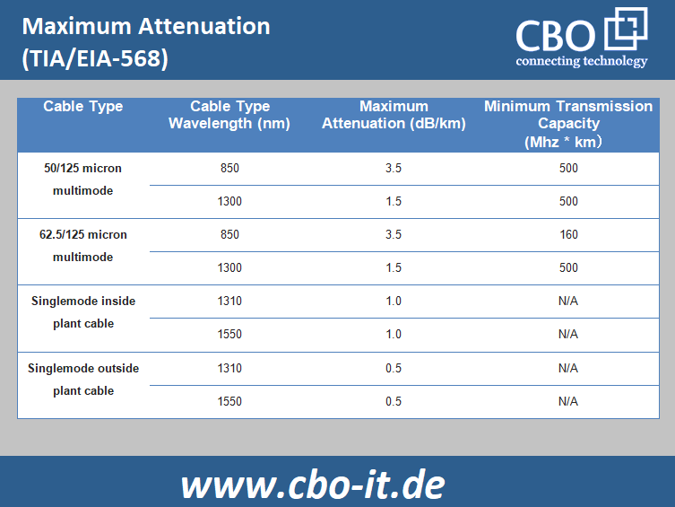
TIA (Telecommunications Industry Association) is a regulatory body that specifies performance requirements for connectors and cables used in the construction of optical fiber links. The reference values provided in the TIA standards must be followed by all cable and connector vendors.
Generally speaking, the documentation that comes with optical fiber cable or connectors contains complete information about the technical specifications and the expected losses. The attenuation or fiber loss is measured in dB per kilometer (dB/km). In case if your cable manufacturer hasn’t provided you with the required documentation than you can use the fiber loss reference values as defined by the TIA.
Optical Fiber Losses Calculation
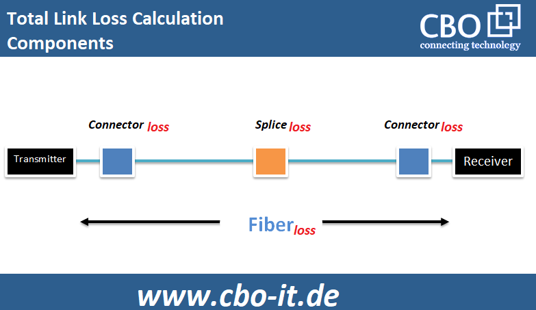
Calculation of optical fiber can easily be done through simple mathematic calculations provided that you have the right equipment available. As we have mentioned above, each optical fiber component and cables are supplied with detailed characteristics. The following simple formulas are used for the calculation of loses across an optical fiber link;
- Total Link Loss = Connector Loss + Cable Attenuation + Splice Loss
- Cable Attenuation (dB) = Length (km) x Attenuation Coefficient ( dB/km)
- Connector Loss (dB) = No. of Connector Pairs x Loss Allowance per connector (dB)
- Splice Loss (dB) = No. of Splices x Loss Allowance per splice (dB)
Please note that the total link loss is just a sum of various notable losses within a fiber link. It must be understood that the total link loss we calculate through the mathematical means cannot be considered more than estimation. So, the actual loss could be lower or higher depending on various factors; including (but not limited to) the operating temperatures, hardware integrity, type of fiber, number of turns, etc.
Worked Example:
Consider that we have an optical fiber link consisting of an SMF that measures 8k m and uses a 1310nm band for optical transmission. The assumed link has 2 x ST connector pairs and 1 x splice. So let us proceed with the calculations using the above-mentioned formulas;
- Fiber Attenuation Loss Calculation;
According to the standard reference, values chart the light attenuation of 1310nm single-mode optical cable is 0.5dB/km. thus, the total cable attenuation according to the formula is; 0.5dB/km x 8km = 4dB.
- Total Connector Loss Calculation;
Using the maximum defined values by TIA/EIA the loss per pair is 0.75. Hence the total connector loss in this case according to the formula is; 0.75dB x 2 = 1.5dB. In practical calculation, the values defined by the connector manufacturer must be utilized.
- Total Splice Loss Calculation;
For this calculation, we will use the maximum splice loss values as defined by the TIA/EIA i.e. 0.3 per splice. So, for this link which has one splice the total splice loss according to the above-mentioned formula is going to be; 1 x 0.3dB = 0.3dB.
- Total Link Loss Calculation;
As described earlier, the total loss across an optical fiber link can be obtained by summing cable attenuation, splice loss, and connector loss. For this link the total loss is; 4dB + 1.5dB + 0.3dB = 5.8dB
Please note that OTDR tracing of an established optical fiber link is the most accurate and easiest method available for total link loss calculation.
Power Budget Calculation
Now, as we have learned about link loss calculation let us proceed with power budget calculation. The link loss value is closely related to the power budget. The comparison between the total link loss and the power budget indicates the reliability of an optical fiber link. The link will operate as desired only if its link loss is within the loss budget. The power budget (PB) is the difference between the receiver`s sensitivity (PR) and transmitter output (PT). For power budget calculation we have a simple formula;
PB = PT – PR
Consider that the transmitter output power is – 12dBm and the receiver sensitivity is -25dBm, the power budget is going to be; -12dBm – (-25dBm) = 13dBm.
Power Margin Calculation
After calculating the link loss and determining the power budget, we can calculate the power margin also. The power margin is often considered as a safety margin as well and it represents the amount of effective power available after compensating or subtracting total link loss from the available power budget. We can easily calculate the power margin using this expression.
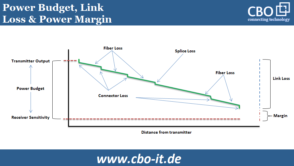
Power Margin (PM) = PB – LL
Take the above mentioned 8km SMF case as an example. The link loss we calculated for that case is 5.8dB and the power budget is 12dB. Thus, the safety margin or the power margin for that particular (hypothetical) optical fiber link is; 13dB – 5.8dB = 7.2dB.
Generally speaking, it is considered that a positive power budget or safety margin value of an optical fiber link indicates that it has the required power available for transmission. So, in this case, our link has a safety margin of 7.2dB and it is going to perform as desired.
Conclusion
It is impossible to construct and operate an ideal optical fiber system with zero losses. The net loss across an optical fiber based link can easily be determined with the help of equipment called OTDR. However, a rough estimation of fiber link loss is also possible through simple arithmetic calculations. These calculations involve certain parameters like cable and connector maximum attenuation. After determining the power loss across a link, we can calculate its power budget and safety margin as well. To ensure safe transmission of data across an optical link its power margin should always remain greater than the available power.


