 English
 Deutsch
 Espaniol


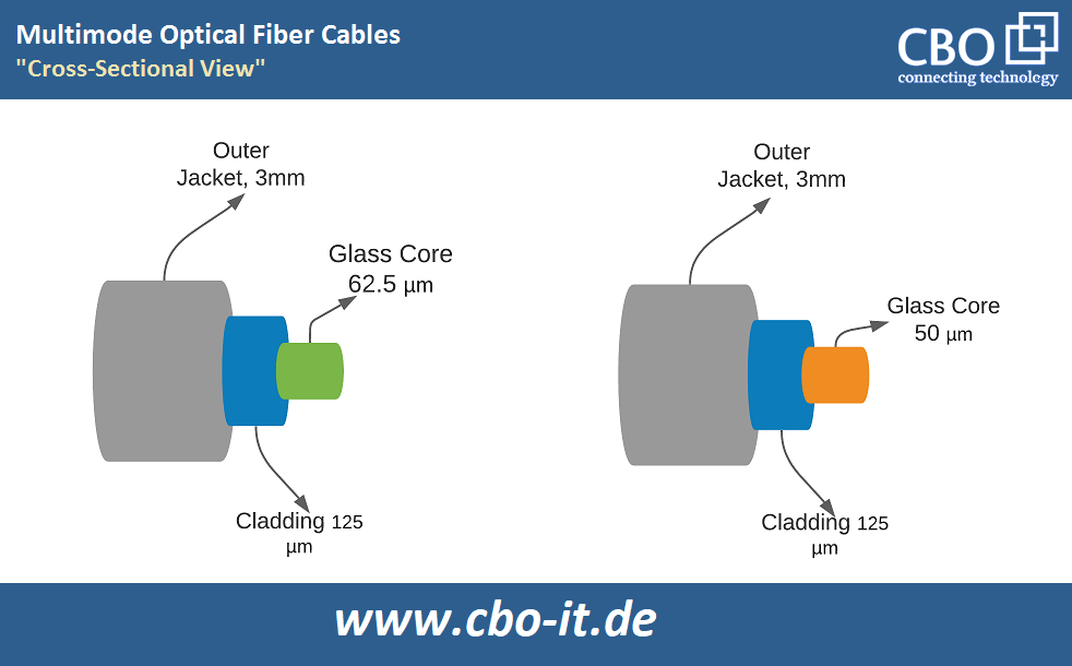
50/125μm and 62.5/125μm fibers are commonly referred to as multimode fibers. The inner diameter of the plastic or glass core inside the optical fiber cable is 50 micrometers and 62.5 micrometers, respectively. The light that encodes your data travels through the fiber core. The 125m refers to the cladding's diameter, which limits the light to the core. The two, available kinds of multimode optical fiber cables are shown in cross-section. Varying bandwidths will result from the different core sizes. Because of the reduced core size, there will be more bandwidth.
The ISO 11801 standard divides multimode fiber into five categories;
- OM1 fiber
- OM2 fiber
- OM3 fiber
- OM4 fiber
- OM5 fiber
Only OM1 fiber is 62.5/125μm, whereas the other four are 50/125μm fibers. Multiple light modes can be propagated in the fiber core at the same time with multimode fiber. The above-mentioned classes of multimode fiber (MMF) differ in data throughput, transmission distance, color, and other characteristics due to differences in core size or bandwidth. The smaller the core size, the greater the data rates and the longer the transmission distance of a fiber cable.
Why Do We Need to Mix Multimode Optical Fibers?
In 10/100Mbps Ethernet, light-emitting semiconductor (LED) reflective surfaces and 62.5m fibers are typically employed. Vertical-cavity surface-emitting laser (VCSEL) – a modern option of light sources, is supposed to enhance the network for increased levels. Even though VCSELs can shift quicker than LEDs, they are better for increased data rates. In consequence, 50m fibers are more commonly used than 62.5μm fibers for beneficiaries’ lengths. As a result, instead of the older 62.5/125μm fibers, most premises installations now use laser-optimized 50 μm or 125μm fiber for 1 to 100 Gigabit Ethernet. Existing fiber cable networks, on the other hand, still use 62.5μm fibers in several applications, necessitating a lot of mixing of the 62.5μm and 50μm fibers.
What Problems May Occur in Mixing Multimode Optical Fibers?
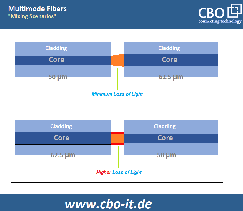
There are two times when a 62.5/125μm multimode fiber and a 50/125μm multimode fiber should be mixed. One is that light must travel from the 50/125μm fiber to the 62.5/125μm fiber, and the other is that light must travel from the 62.5/125μm fiber to the 50/125μm fiber.
So, how do you know if a hybrid connection with a smaller coupling loss is feasible? The conventional limits for mismatch coupling losses are defined in various papers, such as Delmar's Fiber Optic Technicians Manual, which specifies a range of 0.9 to 1.6 dB when combining 62.5/125μm multimode fiber with 50/125μm multimode fiber. It is not suggested to mix 62.5μm fibers with 50m fibers if the real loss exceeds the range.
In the first scenario, the 50/125μm fiber's smaller core may easily couple to the 62.5/125μm fiber and is unaffected by offset or angular misalignment. As a result, there will be almost no issues. However, when switching from a 62.5/125μm multimode fiber to a 50/125μm multimode fiber, one major issue, link failure, may arise. When a 62.5/125μm multimode fiber is mixed with a 50/125μm multimode fiber, light from the 62.5/125μm fiber can escape into the 50/125μm multimode fiber's cladding, resulting in coupling loss. If the loss is significant, blending the 62.5μm and 50μm fibers is not an option.
Possibility of Mixing the 50μm and 62.5μm Fibers
Even though there is an allowed range of mismatch coupling losses, without actual practices, it is impossible to predict how real losses will be. Many tests have been set up in such instances to establish if the mismatch is trustworthy in the majority of occurrences.
Several groups of testing connecting 50μm multimode fibers to 62.5μm multimode fibers from FOA show that LEDs lose more than VCSELs, and the VCSEL has somewhat less excess loss at 20 meters than at 1 meter or 520 meters. The tests with LEDs failed because the coupling losses were over the permitted range between 0.9 and 1.6 dB. All of the experiments using a VCSEL light source succeeded.
Corning also contributed to the capability and reliability of blending 50m and 62.5m multimode fibers, in addition to FOA. Corning, unlike the FOA, has conducted hundreds of experiments to make the results more practical and useful. In both laser and 800nm/1300nm LED sources, the Corning testing indicated no substantial coupling losses.
Although thousands of studies have shown that 50m and 62.5m fibers are entirely compatible with laser sources, industry standards, leading media, and equipment manufacturers advise against mixing multiple kinds of fiber in a single link. They advise you to prepare for the worst and expect a significant loss in one way. Of course, if you can live with the loss, you may combine the 62.5μm and 50μm fibers without difficulty.
MMF Compatibility at Varying Bandwidths
Multimode optical fiber compatibility of different bandwidths or from distinct providers is equally important, regardless of fiber compatibility when mixing 62.5μm and 50μm fibers. For example, fiber compatibility of multiple bandwidths is critical if you wish to use older 62.5μm fiber to boost overall network bandwidth without mixing 50μm fiber. Companies like Corning have demonstrated that blending fiber bandwidth types is theoretically achievable in instances where it is inevitable. However, as long as the fibers and linkages are standard-compliant, fibers from different manufacturers are interoperable.


