 English
 Deutsch
 Espaniol


Numerous tests are done by vendors during the designing and production phase of fiber patch cables to ensure the shipping of high-quality patch cables only. These optical fiber tests are crucial for every type of optical fiber network. It is necessary for the vendor as well as for end-users to learn and understand the tests which are done to determine the quality of the fiber patch cable and the result of these tests is evaluated to decide whether the fiber patch cables under consideration are suitable for your application or not. In this post we are going to talk about the three most important tests; insertion loss (IL) test, 3D metrology test, end-face clarity, and return loss (RL) test.
1. Insertion Loss (IL) & Return Loss Test
Insertion Loss or IL is the signal power loss caused by the installation of an in-line optical device or equipment within a data transmission line. Whereas, Return Loss or RL is defined as the loss in signal power due to the reflection towards the light source. In the following passages, you will find some useful information regarding the Return and Insertion Loss of optical fiber connectors.
Return Loss and Insertion Loss are two very crucial parameters for both vendors and network operators. It is important for vendors that the insertion loss and return loss values of their products should comply with the industrial standards. As an example, consider the TIA standard according to which the maximum insertion loss across an optical fiber connector should not exceed 0.75dB in the worst-case scenario. However, they have defined a range of 0.15 to 0.20dB for low loss and 0.30 to 0.50dB for standard loss.
The use of RL and IL meters or testers is the most common method being utilized by the vendors to assure that the maximum loss values of their designed and manufactured products are within the defined or allowable limits. Testing of optical fiber components such as cables and connectors can also be done by the end-user provided that they have the required tools and testers available.
Techniques like OFDR and OTDR help installers identify and troubleshoot faulty networking components.
2. Endface Clarity
The importance of end face clarity or cleaning is often addressed when it comes to optical fiber systems maintenance. Here, the term “end face” actually refers to the end-face of the optical fiber connectors. Most manufacturers do inspect the end face before dispatching parts to confirm that there are no contaminants, cracks, or scratches. Optical fiber network maintenance team members are used to carry a cassette cleaner or pe cleaner with them. These simple tools are frequently employed for the cleaning of connector end-faces before installation.
- The Significance of Endface Clarity
The smoothness and cleanliness of the optical fiber connector end-face are considered as one of the most important and basic parameters for the quality assurance of optical fiber network links. Even microscopic dust particles, debris, oil, moisture, or other contaminants on the enface of a connector can result in an increased return loss or even permanent damage to the connector. Moreover, the presence of dust between two end faces can lead to the formation of an air pocket or misalignment between optical fiber cores – a condition that can lead to serious degradation of the optical signal. The presence of microscopic contaminants on the surface of the end-face of a connector cannot be observed without a microscope. Mating a dirty or contaminated connector with a clean connector can result in the contamination of the latter. Thus, cleaning of connector end-faces is recommended each time when they are mated or even after the un-mating.
3. 3D Metrology Test:
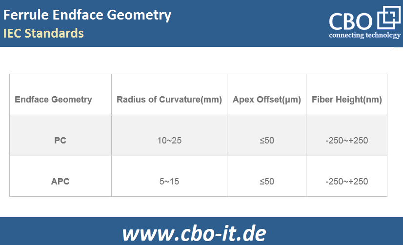
3-dimensional surface measurement or 3D metrology is an important test done for controlling optical fiber connectors' performance. 3D metrology tests are conducted with the help of a specially designed instrument called a 3D interferometer. With the help of a 3D interferometer, vendors can inspect the end face of the optical fiber connectors in detail to keep the end face dimensions within desired ranges. Apex offset, the radius of curvature, and fiber height are the three main characteristics that are measured through 3D metrology testing. The following exhibit contains IEC recommended values for various parameters related to the ferrule end-face geometry.
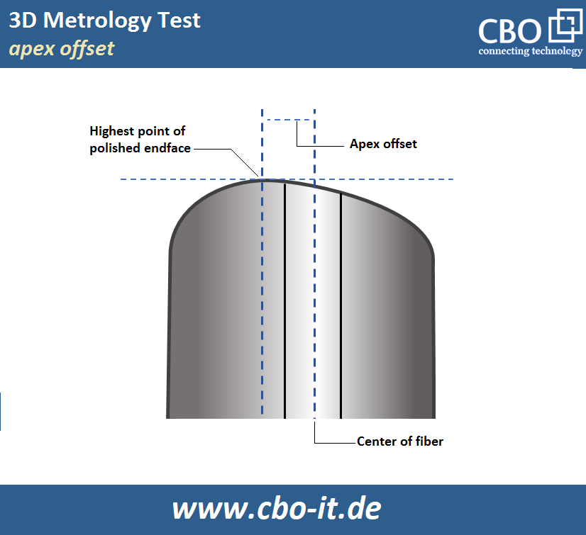
- Apex Offset
It is the linear distance between the center of fiber and the uppermost point of the optical fiber connector`s polished ferrule end face. The maintenance of desired apex offset is ensured during the polishing process of the end-face. Here, it is important to understand that improper or incorrect polishing can lead to abnormal apex offset values.
Theoretically, a perfect core-to-core connection should be achieved when two connectors with centered apex offset are mated and there should be an air pocket in-between. A large apex offset could lead to the formation of an air pocket resulting in high return loss and insertion loss. Optical fiber connectors with UPC or PC ferrules should be polished with an apex offset value of 0. To achieve a perfectly centered apex, the ferrule must be held exactly perpendicular to the polishing surface. In the case of APC ferrules, the recommended angle between the fiber and the ferrule is 8 degrees.
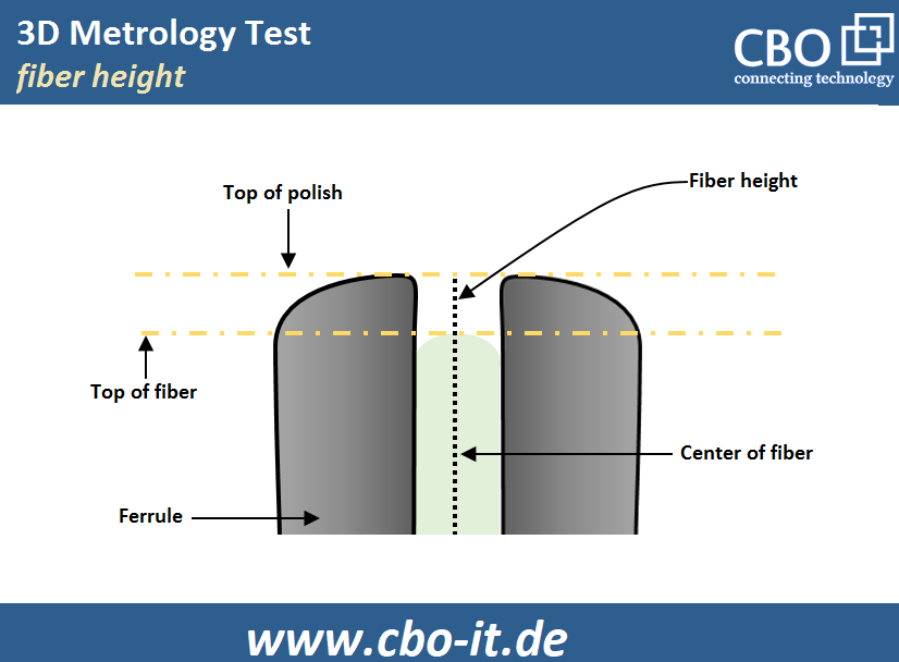
- Fiber Height
The term “fiber height” refers to the distance between a fiber core and the surface of the ferrule. The fiber height should not be too low or too high. In case of a too low fiber height, increased insertion loss (IL) can be experienced because of the formation of an air gap or air pocket between mated connectors. whereas, excessive fiber height can lead to wear and tear or even damage of fiber core during mating/unmating cycles.
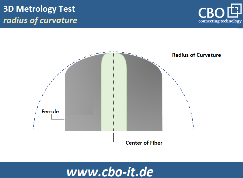
- Radius of Curvature
As shown in the image below, the radius of curvature (ROC) is the roundness of an optical fiber connector`s ferrule end face. The ROC of a fiber patch cord end face must not exceed the defined range. The recommended ROC ranges for APC and PC connectors are 5mm to 15mm and 10mm to 25mm respectively. Ferrules with an excessive radius of curvature value cannot deform enough to ensure a precise physical connection between fibers and ferrules with a smaller radius of curvature tend to damage or crush the fibers after repeated cycles of plugging and unplugging.
Conclusion
- Robust physical contact between fibers is vital to ensure high RL and low IL.
- Spherical end faces help in ensuring physical contact between fibers
- 3D metrology tests provide valuable information about the end face geometry
- Insertion Loss (IL) and Return Loss (RL) test results can indicate end face related issues
- Apex offset, the radius of curvature and apex offset are critical end face geometry parameters
- Endface clarity is important and can be ensured with the help of a pen or a cassette cleaner


